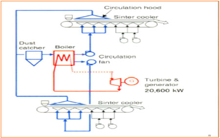
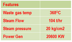
20.6 MW waste heat recovery system on Sinter straight-line Cooler in Sinter Machine 1 &2
- The hot sinter at 700 - 750OC at sinter machine outlet is cooled by blowing air through blower fans.
- The sensible heat energy is presently lost to atmosphere and will be recovered by installing waste heat recovery system which consists of circulation fan, waste heat boiler (generation of steam) and steam turbine (to generate electricity).
- System expects to generate 20.6 MW of Electricity.
- Reduces dust emission in the vicinity of plant.
- RINL implemented this project with technological cooperation from NEDO of Japan under green aid plan.
- Generates electricity with out using any fossil fuels and reduces demand from captive power plant and Grid.
 |
  |
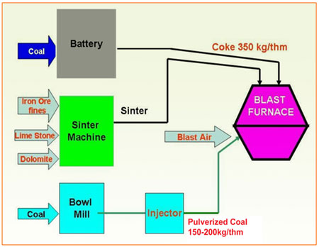
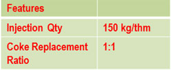
Pulverized Coal Injection (PCI) System in Blast Furnace 1, 2 & 3
- Injecting pulverized coal directly through the blast furnace tuyeres as a partial substitute for the coke used in the blast furnace.
- By Injecting pulverized coal directly, the corresponding amount of coke is reduced, making it possible to reduce energy consumption for coke making (coke dry distillation energy) and reduce GHG emissions.
- The equipment comprises of (1) coal receiving equipment, (2) pulverizing/drying equipment, (3) pulverized coal injection equipment and the instrumentation system.
- This coal is pulverized and conveyed to the pulverized coal storage silo. It is then supplied at the timing of injection in accordance with the injection rate.
- The injection tank is pressurized with a compressor, and the pulverized coal is conveyed to the blast furnace tuyeres (charging holes) and injected into the blast furnace using this pressure.
- Reduces GHG emissions of coke ovens, Decreased frequency of BF relining, High reliability and easy operation, Increased productivity.
 |
  |
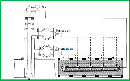
Energy efficient burners in Sinter ignition furnace in Sinter Plant-2
- Sinter Machine-3 is envisaged with energy efficient burners which can achieve uniform ignition in the pallet width direction and rapid heating has been introduced to realize reduction of fuel consumption.
- This burner consists of fuel exhaust nozzles located in the sintering floor width direction and a slit-like burner tile containing these fuel exhaust nozzles. The fuel supplied from the fuel exhaust nozzles reacts with the primary air inside the burner tile, then with the secondary air supplied to flame outer periphery area.
- By using the slit-like burner tile, non-flamed places can be eliminated, and by controlling the ratio between the primary air and the secondary air, the length of the flame can be controlled to minimize the ignition energy.
- Reduces fuel consumption and reduces GHG emissions.
- RINL is also installing similar feature in Revamping of Sinter Machine 1 &2.
 |
  |
Waste Heat Recovery system in Sintering Plant-2
- Sintered ore discharged from the sintering machine has the temperature of 700 - 750OC, and cannot be transported directly to the blast furnace. Therefore, the air-cooling-type cooler is installed at the exit of the sintering machine. The sensible heat of the high-temperature part (250 - 450OC) of the cooler exhaust gas is recovered as
- Recycled as process heat in to Sinter Machine( Extended Hood) and Combustion air to ignition Furnace Burners in sintering plant-2
- Recycling of hot air as process heat is environmental friendly as it reduces heat requirement to ignition furnace , reduce dust emission and reduce GHG emission.
 |
  |
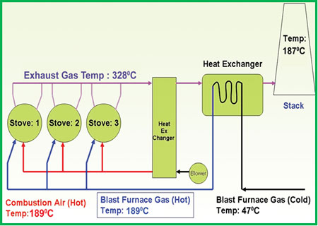
Blast Furnace Stoves Waste heat recovery
- The Waste gases generated during combustion process at BF Stoves are released in to atmosphere in conventional systems and results in loss of heat.
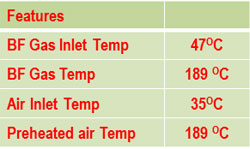
- Waste Heat Recovery system recover the sensible heat of the flue gas generated in heating the hot stoves which supply hot blast to the blast furnace and uses this heat in preheating fuel and combustion air for the hot stoves.
- This device consists of counter current heat exchanger wherein outgoing flue gases sensible heat is recovered by the incoming fuel gas and combustion air. The fuel gas and combustion air are pre-heated and supplied to the Blast Furnace stoves.
- The exit temperature of the flue gases, reduces from 328OC to 189O c
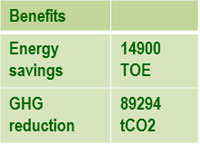
- Installation of this device improves the combustion efficiency of the hot stoves, thereby saving energy and reducing GHG emissions.
 |
  |
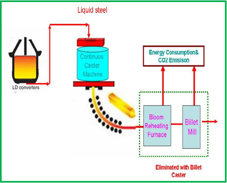
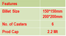
Billet Caster in Steel Melt Shop - 2
- RINL envisaged Continuous Casting Machine to produce blooms in existing facilities thereby reducing energy consumption as compared to Soaking Pit Practice.
- In the continuous casting process, molten steel from converter is introduced into a device called a tundish, from which it is poured into a mold.
- The molten steel poured into the mold descends through the Continuous Casting Machine between guide rolls while water cooling is applied.
- Con Cast Blooms in energy efficient process over soaking pits. However, 0.53 Gcal of energy is spent to reheat the blooms.
- Instead of this two step process, RINL is installing Billet caster to produces billets of 150 X 150 mm and 200 X 200 mm range, there by reducing energy for heating of blooms for rolling in to Billets and will reduce GHG emissions.
 |
 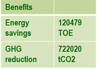 |
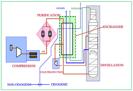
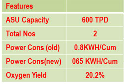
Energy Efficient Air Separation Units
- Utilities such as oxygen and Nitrogen are produced by separation of Air in Air Separation Plant. The constituents of air to be separated by means of rectification. Rectification is a distillation process that enables the individual components to be obtained with a high purity and good yield.
- In the conventional distillation columns, the distillation is fractional tray by tray and each will be a theatre of cooling and partial condensation of the rising vapour of Heating and partial vaporization of the descending liquid
- Thus the distillation tray provides the rising gas with a certain resistance (creating a loss of load) which the rising vapour has to overcome.
- In the modern ASUs the distillation columns are equipped with packing. The distillation packing offers less resistance than if it was equipped with trays thereby saving energy.
- Improvement in oxygen yield by 16%
- Heat energy for regeneration of adsorbent is reduced by selection of better quality of adsorbents
 |
  |
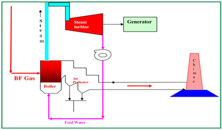
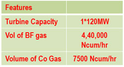
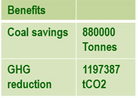
120 MW BF gas based captive power plant-2
- Installation of Blast Furnace -3(2.5 Mtpa) and Up gradation of existing Blast furnaces to 2.5 Mtpa each results in likely surplus of BF gas with lower heat value. Utilization of low BF gas which generates large quantity of flues gases and less thermal efficiency.
-
Utilizing Surplus waste BF gases for generation of electricity in 120 MW CPP-2 with
- Design to fire low calorific value gases
-
Improved burner design in boilers
- Low volumetric heat release rate with larger boiler furnace (higher residence time & higher heat surface area).
- Scroll type burner (provides spin to the BFG at the point of air fuel mixing)
- Adequate refractory lining on water wall tubes of furnace heat surface and it will reradiate heat into the flame.
- Low flue gas temperature (155OC)
- Lower heat release rate
 |
  |
Waste Heat Recovery systems in reheating furnaces and calcination plant in Expansion Units
Steel Industry Reheating Furnaces and Calcination Plant Lime Kilns releases waste energy at temperature of 550-700 OC from their reheating furnaces. The hot sensible energy of waste gases is recovered in heat exchangers and combustion air is preheated. With the result, the exit gas temperature of waste gases is reduced to less than 300 OC thereby reducing heat loss through chimneys . The heat recovered through heat exchangers is ploughed back in to combustion systems and reduces fuel input to the furnaces and reduce GHG emissions.